WO2024143563A2 - 物品収納箱 - Google Patents
物品収納箱 Download PDFInfo
- Publication number
- WO2024143563A2 WO2024143563A2 PCT/JP2024/015572 JP2024015572W WO2024143563A2 WO 2024143563 A2 WO2024143563 A2 WO 2024143563A2 JP 2024015572 W JP2024015572 W JP 2024015572W WO 2024143563 A2 WO2024143563 A2 WO 2024143563A2
- Authority
- WO
- WIPO (PCT)
- Prior art keywords
- storage box
- item storage
- cut
- box according
- main body
- Prior art date
Links
- 238000003860 storage Methods 0.000 title claims abstract description 242
- 239000003205 fragrance Substances 0.000 claims description 24
- 238000005452 bending Methods 0.000 abstract description 17
- 239000000428 dust Substances 0.000 abstract description 7
- 230000015572 biosynthetic process Effects 0.000 abstract 3
- 238000000605 extraction Methods 0.000 abstract 2
- 239000000123 paper Substances 0.000 description 26
- 230000001965 increasing effect Effects 0.000 description 23
- 238000010586 diagram Methods 0.000 description 7
- 230000000694 effects Effects 0.000 description 7
- 238000004519 manufacturing process Methods 0.000 description 4
- 230000001737 promoting effect Effects 0.000 description 4
- 238000005728 strengthening Methods 0.000 description 3
- 239000002699 waste material Substances 0.000 description 3
- 230000002708 enhancing effect Effects 0.000 description 2
- 230000007613 environmental effect Effects 0.000 description 2
- 238000003780 insertion Methods 0.000 description 2
- 230000037431 insertion Effects 0.000 description 2
- 238000000034 method Methods 0.000 description 2
- 230000001151 other effect Effects 0.000 description 2
- 239000002985 plastic film Substances 0.000 description 2
- 229920006255 plastic film Polymers 0.000 description 2
- 239000000463 material Substances 0.000 description 1
- 238000012986 modification Methods 0.000 description 1
- 230000004048 modification Effects 0.000 description 1
- 239000004033 plastic Substances 0.000 description 1
- 230000037303 wrinkles Effects 0.000 description 1
Images


Classifications
-
- B—PERFORMING OPERATIONS; TRANSPORTING
- B65—CONVEYING; PACKING; STORING; HANDLING THIN OR FILAMENTARY MATERIAL
- B65D—CONTAINERS FOR STORAGE OR TRANSPORT OF ARTICLES OR MATERIALS, e.g. BAGS, BARRELS, BOTTLES, BOXES, CANS, CARTONS, CRATES, DRUMS, JARS, TANKS, HOPPERS, FORWARDING CONTAINERS; ACCESSORIES, CLOSURES, OR FITTINGS THEREFOR; PACKAGING ELEMENTS; PACKAGES
- B65D83/00—Containers or packages with special means for dispensing contents
- B65D83/08—Containers or packages with special means for dispensing contents for dispensing thin flat articles in succession
Definitions
- the present invention relates to an item storage box in which multiple items are stored in a stacked state.
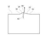
- the fold line 34 describes a circular arc or an elliptical arc.
- the curve rate of the fold line 34 is smaller than the curve rate of the fold line 32.
- the curve ratio of the fold line 34 is preferably 1/4 or more and 3/4 or less of the curve ratio of the fold line 32.
- the definition of the curve ratio of the fold line 34 is the same as the definition of the curve ratio of the fold line 32.
- the curve of the fold line 34 is smaller than the curve of the fold line 32. Making the curve of the fold line 34 smaller in this way is also advantageous for making the folding piece 24 easier to fold. This makes it easier to ensure a wide gap 50 between the folding pieces 22 and 24 in the height direction of the main body 10. From this perspective, it is preferable that the curve of the fold line 34 is 3/4 or less of the curve of the fold line 32. On the other hand, if the curve of the fold line 34 is too small, the bending angle of the folding piece 24 may become excessive. From this perspective, it is preferable that the curve of the fold line 34 is 1/4 or more of the curve of the fold line 32.
- the widths of the side surface portion 132 and the side surface portion 134 are greater than the widths of the side surface portion 136 and the side surface portion 138.
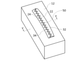
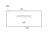
- the top surface portion 140 is provided with an outlet forming portion 20.
- the configuration of the outlet forming portion 20 is as described in the first embodiment. However, in this embodiment, detailed illustration of the outlet forming portion 20 is omitted.
- the main body 110 is configured so that it can be deformed into a bottom-up state.
- the main body 110 can be made of, for example, cardboard or other paper.
- the length of the tongue 172 is preferably 1.1 times or more, more preferably 1.2 times or more, of the distance d10 (see FIG. 8) from the side portion 132 to the side portion 134.
- the length of the tongue 172 is preferably 1 cm or more greater than the distance d10, more preferably 2 cm or more greater.
- the length of the tongue 172 is the maximum dimension of the tongue 172 in a direction perpendicular to the side portion 132 when the tongue 172 is spread on a plane parallel to the bottom portion 120.
- the length of the tongue 172 is equal to the sum of the length d11 of each bottom cut portion 151, 152 and the length d12 of each side cut portion 154, 155.
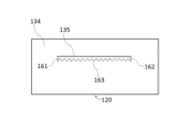
- the slit portion 180 is a portion that is located in the middle of the side portion 134 and that becomes a slit 182 into which the tongue piece 172 can be inserted when a cut is made in the main body 110 (side portion 134) along the cut line 160.
- the slit 182 is a horizontally long opening that extends parallel to the bottom portion 120.
- the tongue piece 172 is configured to be parallel to the bottom portion 120 when inserted into the slit 182.
- the side portion 134 is provided with a fold line 135 for folding the portion 180a surrounded by the cut line 160 (vertical cut portion 161, vertical cut portion 162, and horizontal cut portion 163) to the outside of the main body 110.
- the tongue 172 can be inserted into the slit 182 so that the item is placed on the tongue 172, and the bottom of the item storage box 2 can be raised while the tongue 172 is in surface contact with the item. Therefore, an item storage box 2 that can stably support items when the bottom is raised is realized without providing a bottom-raising member separate from the main body 110.
- the tongue 172 is connected to the side portion 132 without being separated from the main body 110. In this case, a part of the tongue 172 is fixed to the side portion 132, which makes it difficult for the tongue 172 to accidentally come out of the slit 182.
- Increasing the distance h11 from the bottom surface portion 120 to the slit portion 180 in the height direction of the main body 110 is advantageous in terms of enhancing the bottom-raising effect of the item storage box 2. From this perspective, it is preferable that the distance h11 is equal to or greater than 1/2 of the height h10 of the main body 110. On the other hand, if the distance h11 is too large, the amount of items that can be stored in the item storage box 2 after deformation will be extremely small. From this perspective, it is preferable that the distance h11 is equal to or less than 4/5 of the height h10.
- the bottom cut portions 151 and 152, and the side cut portions 154 and 155 are all in a straight line. This makes it easy to make cuts along the bottom cut portions 151, 152 and the side cut portions 154, 155.
- the side cut portions 154 and 155 extend in the height direction of the main body 110. In this case, the length of each side cut portion 154, 155 can be minimized. This also makes it easier to make cuts along each side cut portion 154, 155.
- the bottom cut portion 153 is in a straight line. This makes it easier to make cuts along the bottom cut portion 153.
- the width w11 of the tongue 172 is advantageous for stably supporting items in the item storage box 2 after the bottom has been raised, since the tongue 172 will come into contact with a wider area of the item.
- the width w11 is preferably 1/2 or more of the width w10 of the side portion 132, and more preferably 3/4 or more.
- the width w11 is preferably 9/10 or less of the width w10.
- the width of side portion 132 and side portion 134 is greater than the width of side portion 136 and side portion 138.
- the vertical cut portions 161 and 162, and the horizontal cut portion 163 are all in a straight line. This makes it easy to make cuts along the vertical cut portions 161 and 162, and the horizontal cut portion 163.
- the cut line 160 consists only of the vertical cut portion 161, the vertical cut portion 162, and the horizontal cut portion 163.
- the portion 180a surrounded by the cut line 160 is not cut off from the main body 110, so it is possible to abut the portion 180a against the protruding portion 172a of the tongue piece 172. This makes it even more difficult for the tongue piece 172 to accidentally come out of the slit 182.
- the specific portion 134a can be used as advertising space. By recruiting advertisers, it is possible to earn advertising revenue. If this revenue is used to cover the manufacturing costs of the item storage box 2, the product price of the item storage box 2 can be reduced.
- the specific section 134a is an easily accessible part of the lower section 110a, making it easy to peel off the seal 114.
- Other effects of the item storage box 2 are the same as those of the item storage box 1.
- the tongue 172 has a rectangular shape.
- the tongue 172 may have a tapered shape, for example, as shown in FIG. 15. In this case, it becomes easier to insert the tongue 172 into the slit 182.
- the main body 110 may have a plurality of slit portions 180, for example, as shown in FIG. 17.
- the plurality of slit portions 180 are provided at different positions in the height direction of the main body 110.
- a plurality of fold lines 133 are provided on the side portion 132, as shown in FIG. 18.
- the plurality of fold lines 133 are provided at different positions in the height direction of the main body 110.
- Each fold line 133 is provided at a position overlapping each slit portion 180 in a side view.
- the fold line 133 provided on the upper side of the side portion 132 overlaps the slit portion 180 provided on the upper side of the side portion 134
- the fold line 133 provided on the lower side of the side portion 132 overlaps the slit portion 180 provided on the lower side of the side portion 134.
- the height of the tongue 172 (the distance from the bottom surface 120) can be adjusted by selecting which slit 182 the tongue 172 is inserted into. This makes it possible to select the degree of bottom raising depending on the remaining amount of items. Also, by providing multiple fold lines 133, the tongue 172 can be more easily positioned parallel to the bottom surface 120 regardless of which slit 182 the tongue 172 is inserted into.
- the cut line 160 is located below the fold line 135.
- the cut line 160 may be located above the fold line 135, as shown in FIG. 19.
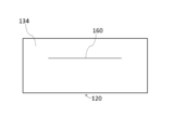
- the cut line 160 is formed along a single non-circular line.
- the cut line 160 may be formed along a single circular line, for example, as shown in FIG. 20.
- the portion 180a surrounded by the cut line 160 is cut off from the side portion 134, and a slit 182 having the same shape and size as the portion 180a is obtained.
- the cut line 160 is formed along multiple line segments.
- the cut line 160 may be formed along a single line segment, for example, as shown in FIG. 21. In the figure, the cut line 160 is entirely in a straight line.
- the cut lines 150 and 160 are perforations. That is, the cut lines 150 and 160 are configured such that the cuts are made along the cut lines 150 and 160 only when force is applied to both sides of the cut lines 150 and 160. However, the cut lines 150 and 160 may be made in advance. Third Embodiment
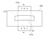
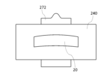
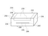
- FIGS. 22 and 23 are perspective views showing a third embodiment of an item storage box according to the present invention.
- FIG. 24 is a bottom view showing the third embodiment of an item storage box according to the present invention.
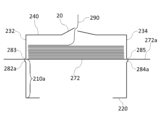
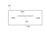
- FIGS. 25 and 26 are side views showing the third embodiment of an item storage box according to the present invention.
- the item storage box 3 is an item storage box in which multiple items are stored in a stacked state, and includes a main body 210.
- the main body 210 is box-shaped and consists of a bottom surface portion 220, a side surface portion 232 (first side surface portion), a side surface portion 234 (second side surface portion), a side surface portion 236 (third side surface portion), a side surface portion 238 (fourth side surface portion), and a top surface portion 240.
- the main body 210 is rectangular parallelepiped-shaped.
- Figures 22 and 23 are oblique views seen from the top surface portion 240 side and the bottom surface portion 220 side, respectively.
- Figures 25 and 26 are side views seen from the side surface portion 232 side and the side surface portion 234 side, respectively.
- the side surface portion 232 and the side surface portion 234 face each other.
- the side surface portion 236 and the side surface portion 238 also face each other.
- the widths of the side surface portion 232 and the side surface portion 234 are greater than the widths of the side surface portion 236 and the side surface portion 238.
- the top surface portion 240 is provided with an outlet forming portion 20.
- the configuration of the outlet forming section 20 is as described in the first embodiment. However, in this embodiment, detailed illustration of the outlet forming section 20 is omitted.
- the main body 210 is configured so that it can be deformed into a bottom-up state.
- the main body 210 can be made of, for example, cardboard or other paper.
- the main body 210 has a cut line 250 (first cut line), a cut line 262 (second cut line), a cut line 264 (third cut line), a cut piece portion 270, a slit portion 282 (first slit portion), and a slit portion 284 (second slit portion).
- the cut line 250 is formed on at least one of the bottom surface portion 220, the side surface portion 232, and the side surface portion 234. In this embodiment, the cut line 250 is formed only on the bottom surface portion 220.
- the cut line 250 is formed along a single circular line as shown in FIG. 24.
- the cut line 250 is a perforation.
- the cutout portions 251 and 252 extend parallel to the side surface portion 232.
- the cutout portion 253 connects one end of the cutout portion 251 to one end of the cutout portion 252.
- One end of the cutout portion 251 and one end of the cutout portion 252 are located in the middle of the bottom surface portion 220.
- the middle of the bottom surface portion 220 refers to the portion of the bottom surface portion 220 other than the edge (the boundary with each of the side surface portions 232, 234, 236, and 238).
- the cutout portion 254 connects the other end of the cutout portion 251 to the other end of the cutout portion 252.
- the other end of the cutout portion 251 and the other end of the cutout portion 252 are located in the middle of the bottom surface portion 220.
- the cutout portions 253 and 254 extend perpendicular to the side surface portion 232.
- the cut line 262 is formed on the side portion 232. As shown in FIG. 25, the cut line 262 is formed along a single continuous line.
- the cut line 262 is a perforation.
- the cut line 262 includes a vertical cut portion 262a (first vertical cut portion), a vertical cut portion 262b (second vertical cut portion), and a horizontal cut portion 262c.
- the cut line 262 consists only of the vertical cut portion 262a, the vertical cut portion 262b, and the horizontal cut portion 262c.
- the vertical cut portion 262a, the vertical cut portion 262b, and the horizontal cut portion 262c are all straight.
- the vertical cut portion 262a and the vertical cut portion 262b extend in the height direction of the main body 210.
- the length d21 of the segment 272 is preferably 1.2 times or more, more preferably 1.4 times or more, of the distance d20 from the side portion 232 to the side portion 234.
- the length d21 is preferably 2 cm or more larger than the distance d20, more preferably 4 cm or more larger.
- the length d21 is, for example, 14 cm or more and 20 cm or less.
- the length d21 is the maximum dimension of the segment 272 in the insertion direction of the segment 272 into the slit portion 282 and the slit portion 284 described later.
- the length d21 is equal to the length of each of the cut portions 251, 252.
- the width w21 of the segment 272 is preferably 1/4 or more, more preferably 1/2 or more, of the width w20 of the side portion 232.
- the width w21 is, for example, 6 cm or more and 10 cm or less.
- the width w21 is the maximum dimension of the segment 272 in the direction perpendicular to the insertion direction. In this embodiment, width w21 is equal to the length of each cutout portion 253, 254.
- the slit portion 282 is a portion that becomes a slit 283 (first slit) located in the middle of the side portion 232 and into which the piece 272 can be inserted when the main body 210 (side portion 232) is cut along the cut line 262.
- the slit 283 is a horizontally long opening that extends parallel to the bottom portion 220.
- the side portion 232 is provided with a fold line 233 for folding the portion 282a surrounded by the cut line 262 (vertical cut portion 262a, vertical cut portion 262b, and horizontal cut portion 262c) to the outside of the main body 210.
- the fold line 233 connects the other end of the vertical cut portion 262a to the other end of the vertical cut portion 262b.
- the fold line 235 connects the other end of the vertical cut portion 264a to the other end of the vertical cut portion 264b.
- the fold line 235 is parallel to the bottom portion 220. It is preferable that the fold line 235 has a crease formed in advance so that the portion 284a can be easily folded along the fold line 235. However, the fold line 235 may be simply a line printed on the side portion 234 to inform the user of the fold position.
- the distance h21 (see FIG. 25) from the bottom surface portion 220 to the slit portion 282 is equal to or greater than 1/2 of the height h20 of the main body 210.
- the distance h22 (see FIG. 26) from the bottom surface portion 220 to the slit portion 284 is equal to or greater than 1/2 of the height h20.
- the slit portion 282 and the slit portion 284 are formed in positions that overlap each other in a side view.
- the item (tissue paper 290) is placed on the piece 272 as shown in FIG. 31.
- the tissue paper 290 By raising the bottom of the item storage box 3 (main body 210) in this way and bringing the tissue paper 290 closer to the top surface 240, the tissue paper 290 can be smoothly removed from the removal opening even when there is only a small amount of tissue paper 290 remaining.
- the distance from the piece 272 to the top surface 240 is 3 cm or more and 6 cm or less. Note that the tissue paper 290 is not shown in FIGS. 27 to 30.
- the section 270, as well as the slit section 282 and the slit section 284 are provided on the main body 210. From the section 270, the section 272 separated from the main body 210 is obtained. From the slit section 282 and the slit section 284, the slit 283 and the slit 285 are obtained, which are located in the middle of the side section 232 and the side section 234, respectively, and into which the section 272 can be inserted. By inserting the section 272 into the slit 283 and the slit 285, the section 272 can be stretched from the middle of the side section 232 to the middle of the side section 234.
- the cut line 250 is made up of cut portions 251 and 252, as well as cut portions 253 and 254. This allows the cut line 250 for forming the segment 272 to be realized with a simple configuration.
- the cut portions 253 and 254 are in a straight line. This makes it easier to make cuts along the cut portions 253 and 254.
- the vertical cut portions 262a and 262b, and the horizontal cut portion 262c are all in a straight line. This makes it easy to make cuts along the vertical cut portions 262a and 262b, and the horizontal cut portion 262c.
- the cut line 262 consists only of the vertical cut portion 262a, the vertical cut portion 262b, and the horizontal cut portion 262c.
- the portion 282a surrounded by the cut line 262 is not cut off from the main body 210, so it is possible to abut the portion 282a against the protruding portion 272a of the piece 272. This makes it even more difficult for the piece 272 to accidentally slip out of the slit 283.
- the cut line 264 includes vertical cut portions 264a and 264b, as well as horizontal cut portions 264c. This allows the cut line 264 for forming the slit 285 to be realized with a simple configuration.
- the letters or designs are printed on the top surface of the protruding portion 272a. By printing on the top surface, where they are easily visible, the letters or designs can be made to stand out.
- the outlet portion 272a can be used as advertising space. By recruiting advertisers, it is possible to earn advertising revenue. If this revenue is used to cover the manufacturing costs of the item storage box 3, the product price of the item storage box 3 can be kept low.
- Letter or a design is printed on the lower portion 210a of the inner surface of the main body 210.
- the lower portion 210a can be used as advertising space. By recruiting advertisers, it is possible to earn advertising revenue. If this revenue is used to cover the manufacturing costs of the item storage box 3, the product price of the item storage box 3 can be kept low.
- the fragrance section 212 is provided in the lower portion 210a, it is possible to disperse a fragrance around the main body 210 after it has been deformed. That is, by peeling off the seal 214 after the main body 210 has been deformed, the fragrance in the fragrance section 212 can be dispersed around the main body 210. In addition, because the seal 214 is affixed to the fragrance section 212, the user can choose whether or not to disperse a fragrance around the main body 210 by whether or not to peel off the seal 214. Other effects of the item storage box 3 are the same as those of the item storage box 1.
- the shape of the segment 272 is rectangular.
- the segment 272 may have a tapered shape, for example, as shown in FIG. 33.
- the task of inserting the segment 272 can be facilitated by inserting the segment 272 into the slits 283, 285 from the tapered portion.
- the horizontal cut portion 262c of the cut line 262 is shown as a straight line.
- the horizontal cut portion 262c may be wavy, for example, as shown in FIG. 34.
- the piece 272 inserted into the slit 283 can be sandwiched from above and below by the convex portions, making it even more difficult for the piece 272 to accidentally slip out of the slit 283.
- the cut line 264 is formed along multiple line segments.
- the cut line 264 may be formed along a single line segment, for example, as shown in FIG. 43. In the figure, the cut line 264 is entirely straight.
- cut lines 42 cut lines 42a, 42b), 44, and 46
- the portion between cut lines 42a and 42b is cut out from top surface 12. Therefore, even when folding pieces 22 and 24 are not folded, a gap is created between them. This is advantageous for making it easier to remove items smoothly.
Landscapes
- Engineering & Computer Science (AREA)
- Mechanical Engineering (AREA)
- Cartons (AREA)
- Stackable Containers (AREA)
Priority Applications (2)
| Application Number | Priority Date | Filing Date | Title |
|---|---|---|---|
| PCT/JP2024/015572 WO2024143563A2 (ja) | 2024-04-19 | 2024-04-19 | 物品収納箱 |
| JP2024524365A JP7714203B2 (ja) | 2024-04-19 | 2024-04-19 | 物品収納箱 |
Applications Claiming Priority (1)
| Application Number | Priority Date | Filing Date | Title |
|---|---|---|---|
| PCT/JP2024/015572 WO2024143563A2 (ja) | 2024-04-19 | 2024-04-19 | 物品収納箱 |
Publications (2)
| Publication Number | Publication Date |
|---|---|
| WO2024143563A2 true WO2024143563A2 (ja) | 2024-07-04 |
| WO2024143563A3 WO2024143563A3 (ja) | 2024-08-22 |
Family
ID=91718155
Family Applications (1)
| Application Number | Title | Priority Date | Filing Date |
|---|---|---|---|
| PCT/JP2024/015572 WO2024143563A2 (ja) | 2024-04-19 | 2024-04-19 | 物品収納箱 |
Country Status (2)
| Country | Link |
|---|---|
| JP (1) | JP7714203B2 (en]) |
| WO (1) | WO2024143563A2 (en]) |
Cited By (1)
| Publication number | Priority date | Publication date | Assignee | Title |
|---|---|---|---|---|
| WO2025037652A3 (ja) * | 2024-08-30 | 2025-05-08 | 株式会社無有 | 物品収納箱 |
Family Cites Families (7)
| Publication number | Priority date | Publication date | Assignee | Title |
|---|---|---|---|---|
| JPS62132970U (en]) * | 1986-02-17 | 1987-08-21 | ||
| JPH0387690U (en]) * | 1989-12-22 | 1991-09-06 | ||
| JPH04112073U (ja) * | 1991-03-13 | 1992-09-29 | 株式会社マルト長谷川工作所 | テツシユペーパー用ホルダー |
| JPH1086981A (ja) * | 1996-09-12 | 1998-04-07 | Tsutomu Tanizawa | 落ち止めボックス |
| JPH11314687A (ja) * | 1998-05-01 | 1999-11-16 | Toshio Saito | 内容物の残量の安定取り出し可能箱 |
| JP2004059150A (ja) * | 2002-09-05 | 2004-02-26 | Jiro Ishida | ティシューボックス等の取り出し口構造 |
| JP2009184719A (ja) | 2008-02-08 | 2009-08-20 | Daiki:Kk | 取出口片を蓋として使用するティッシュペーパーボックス |
-
2024
- 2024-04-19 JP JP2024524365A patent/JP7714203B2/ja active Active
- 2024-04-19 WO PCT/JP2024/015572 patent/WO2024143563A2/ja unknown
Cited By (1)
| Publication number | Priority date | Publication date | Assignee | Title |
|---|---|---|---|---|
| WO2025037652A3 (ja) * | 2024-08-30 | 2025-05-08 | 株式会社無有 | 物品収納箱 |
Also Published As
| Publication number | Publication date |
|---|---|
| JP7714203B2 (ja) | 2025-07-29 |
| WO2024143563A3 (ja) | 2024-08-22 |
| JPWO2024143563A1 (en]) | 2024-07-04 |
Similar Documents
| Publication | Publication Date | Title |
|---|---|---|
| JP7714203B2 (ja) | 物品収納箱 | |
| US9359107B2 (en) | Card reader accessible multiple transaction card holder | |
| JP5534462B2 (ja) | スタンド付ティッシュペーパーボックス | |
| WO2024117271A2 (ja) | 物品収納箱 | |
| US6474542B1 (en) | Carton with framed opening feature and product viewing window | |
| WO2024090588A2 (ja) | 物品収納箱 | |
| WO2024167028A2 (ja) | 物品収納箱 | |
| WO2024085262A2 (ja) | 物品収納箱 | |
| JP4008259B2 (ja) | 商品収納構造および商品収納方法 | |
| JP7296286B2 (ja) | 包装箱 | |
| JP3238503U (ja) | カードホルダー | |
| JP2024159950A (ja) | 物品収納箱 | |
| JP2025007072A (ja) | 紙製容器 | |
| GB2498616A (en) | Container for suspension from a clipstrip | |
| JP4183136B2 (ja) | 包装用ケース | |
| JP7261025B2 (ja) | 什器転用型化粧箱 | |
| JP2024164433A (ja) | 紙製容器 | |
| JP5477535B2 (ja) | 展示機能付き紙箱 | |
| JP4999545B2 (ja) | 収納ケース | |
| JPH0245138Y2 (en]) | ||
| JP2007267987A (ja) | 紙製収納箱 | |
| JP4917568B2 (ja) | 包装用ケース | |
| JP2024179045A (ja) | 紙製容器 | |
| JP2024157779A (ja) | 紙製容器 | |
| WO2024150835A2 (ja) | 衛生用紙収納箱 |
Legal Events
| Date | Code | Title | Description |
|---|---|---|---|
| ENP | Entry into the national phase |
Ref document number: 2024524365 Country of ref document: JP Kind code of ref document: A |
|
| 121 | Ep: the epo has been informed by wipo that ep was designated in this application |
Ref document number: 24736972 Country of ref document: EP Kind code of ref document: A2 |